


Indulge an old man for a minute – and learn a new skill in the process!
You see, my pal of 71-years (The Major) is in recovery from a knee replacement this week. So, I thought a return to those “thrilling days of yesteryear” might have some curative effects.
The scene-setter, therefore is the old Owens Pharmacy at the intersection of 15th Ave. South and Beacon Ave. South in Seattle circa 1963. Because they had two things of keen interest to young ham radio sorts as we were at age 13 or 14.
In addition to a totally smoking hot pharmacist (long brunette hair, yoga practitioner, too) they also had a tube checker. Sadly, we spent most of our time there with the tube checker.
Back in this era of electronics there were no chips, only a few solid-state diodes, and even most of these were still selenium stacks. But when a radio stopped working, it was – often as not – merely a vacuum tube gone awry. Easily tested…and a useful skill if you want to restore old TVs or Fender amps, for example.
First You Need a Tube Checker
The one at Owens was a counter-height base where a bevy of tubes was kept under lock and key. Those were the store’s inventory. The top was where the testing took place.
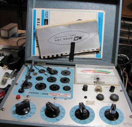
Never to be caught short, I somehow still have three tube checkers, since I’m an old school radio and high-speed Morse code kind of guy. Your “checkout” will be on this one: A B&K Precision DynaJet tester:

The high-level view of the process goes like this:
- Once you have a tube checker, select the suspect tube you want to check.
- Look at the tube number.
- Find the checker/tester settings in the manual.
- Put the tube in the right test socket.
- Read meter and determine if you need to buy a new tube.
It ain’t rocket science, or neither The Major nor I would have been able to figure it out.
Real Life Application
Step into the Radio Detective’s workspace. Here we see that Drake 2B receiver that was resurrected this week. The radio had almost no audio coming out of it. Which didn’t seem to be caused by my defrocking the case from it or running it upside down on the workbench…

Later, it would be found that the previous owner – a member of the Royal Soldering Society, had attempted to replace the specified tube (an 8BN8, which wasn’t terribly common) with something else. In the process, the wiring turned to spaghetti, but a lot of radios coming across my bench seem to be plagued with either soldering idiot or Golden Screwdriver recipients lately – but that’s another column.
Point is, after the 8BN8 tube, the next stop on the way to the speaker is a tube numbered 6AQ5. Real common, generally reliable tube. But you can’t take chances. We measure and test. Like stock trading, measure and look for results, right?
Here’s your first hint at becoming a tube testing expert. When you have a tube where the lettering is not clear, like our 6AQ5 friend here:

You can gently rub the tube on the short hair of your neck and the numbers will become more legible. This seems to work on all the glass tubes I’ve tried it on; it doesn’t work on metal or ceramic tubes, though.
Since the tube was in the 6AQ5 socket in the radio, and it read 6AQ5, the next step was to look it up in the “secret decoder book” for the B&K tester.

Starting with the black arrow, we ignore the previous tech’s note and notice the “Heater voltage” for this baby is 6.3 volts. The “A” knob (*follow the red arrow down) is set to “35” then the “B” set to “1” and “C” to “7” as the knob settings are completed.
Last column (green circle) is the tester socket to plug the tube into.
A double check of everything, then we put it into the tester and wait 12-seconds. Because, say the books, typical warm-up times on this kind of tube run 11-seconds. (The Major would stare at the meter at the drug store tester. I was trying to catch an eyeful of hot brunette…) Eventually the answer was at hand:

If this was going in a balls-to-the-wall small tube amp – where a pair of 6AQ5’s might pretend to do 20-watts between a pair of them – it would have been too weak. Pushing out CW tones for an old man? It was fine. Back into the radio and resume rewiring the 8BN8 into working again. Which happened 45-minutes later.
Radio Detective Story #2
Hallicrafters HT-40 transmitter repair. And another example of when you buy used ham gear on eBay, often as not it won’t work because if it is working, they’d tout that and get more money for it.
You will remember from our gentle introduction to electronics troubleshooting that capacitors usually go first? That’s why these new caps now live in the HT-40.

The old ones which weren’t replaced yet, had failed to ground and taken out two diodes and one power resistor in the (cheaply designed) radio.

 As luck would have it, yes, I do have a deep store of radio parts, so I was able to walk over to the 10-watt power resistor department and find the ideal replacement. While down in the solid-state devices department, there were some high-speed power diodes, too.
By the way, a second ago I referred to the HT-40 as a cheaply made radio – the kind of thing Hallicrafters didn’t do much of. But I’m not the only one with that opinion. See for additional depth the article HALLICRAFTERS HT-40 (wireless-girl.com), She totally rocks old radio gear and her take on the Johnson Pacemaker, which is also in pre-op here, is very close to my own.
Been a busy week in the radio department. Too damn hot to do much outside, and next weekend will be devoted to setting up the more formal-looking ham radio bench. The tentative layout will be four layers of equipment. Low power (QRP) and up to 50-watts on the desk level and then three layers of acacia wood butcherblock style (60-inches long) above.
These were finished out in the shop with 3-4 coats of sanding sealer and then a couple of layers of triple-thick varathane. Elaine popped her head in this week, long enough to say, “You’re not really going to cover that beautiful wood with RADIO gear, are you????”

“Well, um, yeah honey…”
Second layer up will consist of the solid-state gear. One or both of the Icom 761’s, the TS-590, and the TenTec Jupiter plus an MFJ roller inductor tuner for the open-wire antennas.
The third layer will include the Hallicrafters version of the Collins S-Line. An SX-117, the HT-44 and matching power supply, plus the Loudenboomer (HT-45) amplifier. T.O. Keyer. The top row is still undergoing feverish debate. Another Hallicrafters radio? SR-150 is ready. An Icom marine M710 for channelized ops, digital modes, and ALE?
A lot of the time, so far, has been in working out details of the build of the dream radio setup. Like so many things in life, the fixing-to-get-ready takes more time than the actual build itself should. But we shall see. Might get started on it over Labor Day weekend.
Write when you get rich,
George@Ure.net